Description
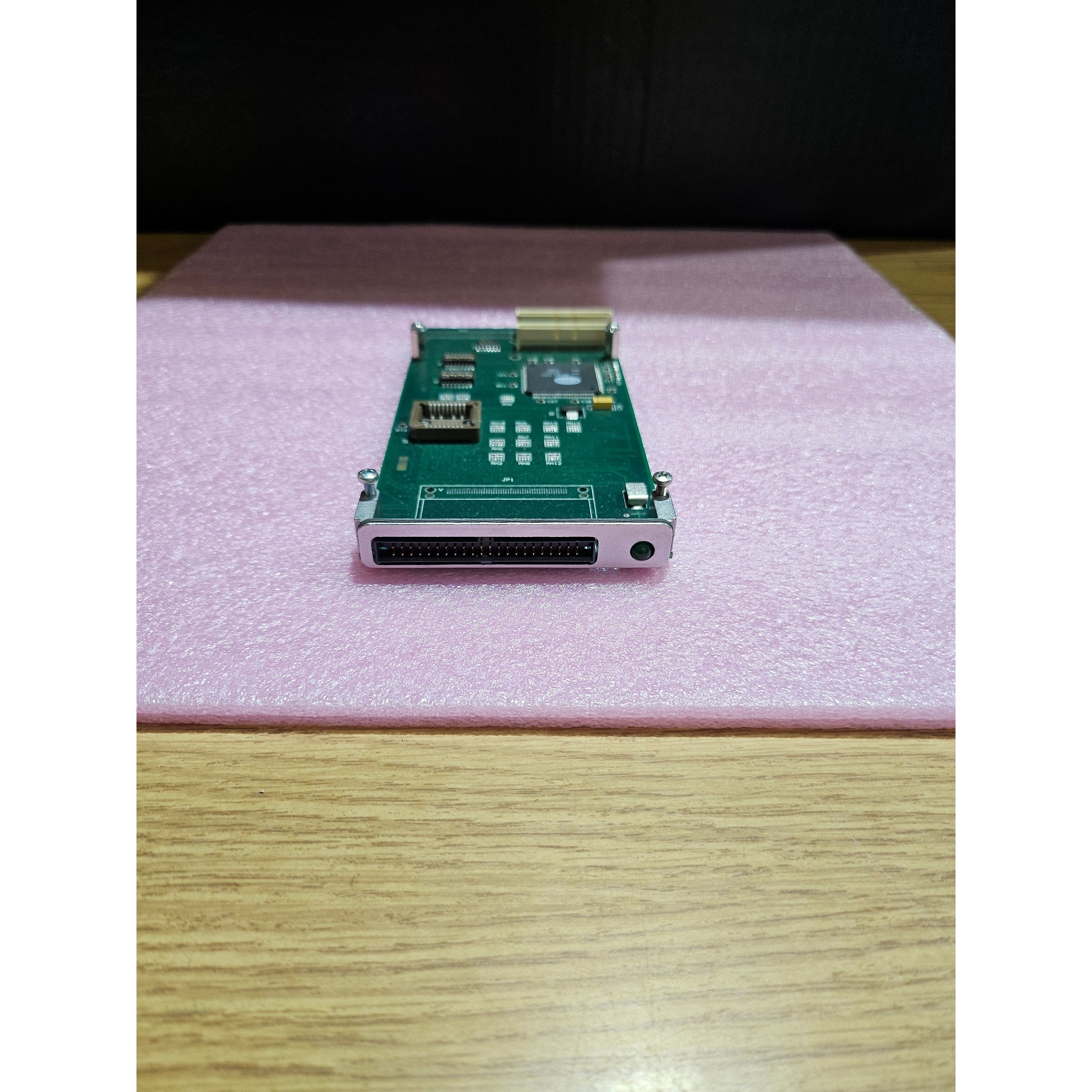
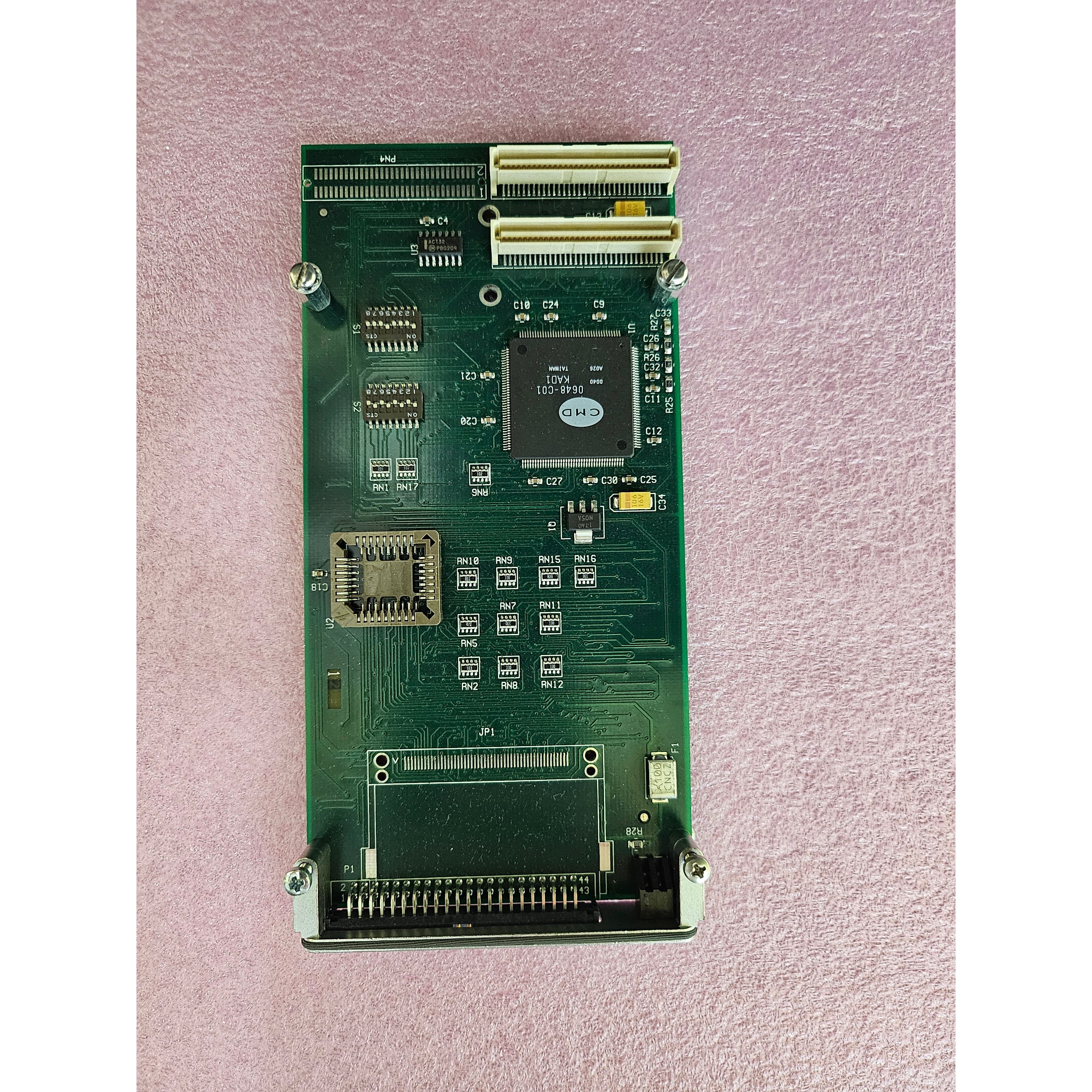
The Front Panel CompactFlash Adapter, when mated
to a host or carrier card, provides an interface between
the PCI bus and a CompactFlash device (Type I or II )
mounted on the Adapter. The Adapter also can interface other IDE/ATA devices, via its rear I/O connector
(PN4) on the Adapter.
Built around a CMD PCI-648 IDE controller chipset,
the product supports the Ultra 66 data-transfer protocol over its IDE channel. It also supports slower busmaster data transfer rates to accommodate hard disk
drives (HDDs) that do not support Ultra 66.
The selected PCI bus is a 32-bit bus at 33 MHz. A built
in phase-lock loop generates an internal 66 MHz clock
from the 33 MHz PCI bus clock. This internal 66 MHz
clock is used to transfer data at the rate of 66 Mb/sec
on to the IDE interface.
The CompactFlash site is configured to operate in true
IDE mode. Additionally, the site can be set to operate
as either master or a slave device.
On-board BIOS, provided by CMD and resident in flash
memory, supports boot up configuration. This feature
is supported only on Intel platforms.
An LED is provided on the Adapter’s front panel to indicate activity. The IDE Controller PMC supports four
interrupts. Interrupt configuration is determined by DIP
switch settings. Default setting is Interrupt A


